|
ROUTING: Achieving Premium Finishes When Routing Acrylic
Routing of acrylic has become one the most popular
methods of plastic fabrication in the sign and
point-of-purchase industries. As the accuracy of
CNC routers continues to improve, additional gains are
being made into the machine building, medical devices and
valve industries. A common quality across all of these
industry segments is the requirement for a premium finished
edge on acrylic without the need for post-routing finishing
operations. Four factors in the routing operation typically
will affect the quality of the cut edge: Tooling,
Programming, Machine Condition and Fixturing. If any one
of these factors is not optimized, it will be extremely difficult
to maintain a consistent, high-quality edge finish. Two
of the factors - Tooling and Programming - will be covered
in this article and the remaining two in a future article.
Tooling
Tooling is a broad topic, but there are some simple guidelines
that can be used to decrease the likelihood of failure
during cutter selection. The first selection criterion for
router tooling is typically diameter. While it is a common
request for tooling diameters to be in the 1/8” to 1/4”
range, designing the parts, fixtures and programs for 3/8”
to 1/2” tooling can dramatically improve surface finishes
and consistency from job to job. A typical result from
increasing cutting edge diameter from 1/4” to 3/8” can be
a drop in surface finish from 40-60 rms to 18-25 rms. This
is usually accompanied by an increased feed rate as well as
better chip extraction. The stability and flute depth offered
by larger diameter cutting tools cannot be overestimated.
That said, it is important to note that there is typically only
a marginal benefit when increasing cutting edge diameters
over 1/2” as long as the depths of cut are not exceeding 2”.
The price-to-performance ratio cannot typically
 support the
use of 5/8” to 1” diameter cutters in sheet stock.
support the
use of 5/8” to 1” diameter cutters in sheet stock. After diameter, cutter configuration is frequently the
second selection criterion for tooling. As a rule of thumb,
the smaller the diameter of cutter that is being used, the
more likely it is that a spiral configuration will yield the
optimum edge finish. While straight flutes typically have
good success in larger diameters (3/8” and above), it is the
spirals that excel when cutting with small diameter tooling.
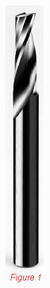
Single edge spiral O-flutes (see Figure 1) typically give
the best edge finishes in 1/4” and smaller tooling. When
moving into the larger diameters, typically low helix multifluted
tools will yield the best results with some
variations, depending on the manufacturing
method of the acrylic (i.e. cast or extruded) and
any fillers that may have been used. It is also in
these larger diameters that the double edge
straights can typically begin to perform well. Both
V-flute and O-flute configurations have been
shown to work well through testing and industry
use. (see Figures 2 & 3)
A final note on tooling is to mention the existence of numerous specialty tools available in the market today.
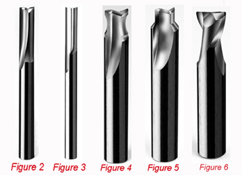 There are products that can be used to provide a radiused edge on parts (Figure4), to rout a finished edge and apply a top chamfer at the same time (Figure 5), or to create a smooth bottom
surface during pocketing without the swirling effects
of standard router bit points (Figure 6). These cutters
either solve problems that have been recurrent in the
industry or allow fabricators to eliminate tool change
cycle times and/or utilize machines without tool changers.
There are products that can be used to provide a radiused edge on parts (Figure4), to rout a finished edge and apply a top chamfer at the same time (Figure 5), or to create a smooth bottom
surface during pocketing without the swirling effects
of standard router bit points (Figure 6). These cutters
either solve problems that have been recurrent in the
industry or allow fabricators to eliminate tool change
cycle times and/or utilize machines without tool changers.
Programming
Selecting the right cutting parameters and cutting
methods is extremely important when edge finish is the
primary driving factor of an operation. Every material and
cutter combination has a “sweet spot” in the cutting
parameters and slight deviations in any direction can
cause an unacceptable decrease in surface finish quality.
Feeds and speeds are typically the best known variables
as far as cutting parameters and they are extremely sensitive
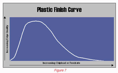
to minor variations. Unlike many other commonly
routed materials, plastics, and particularly acrylics, have
an extremely narrow chip load range that can be used to
produce an optimal finish (see Figure 7). Each cutter
(based on configuration and diameter) will have a different
optimum chip load for each material type. As a rule of
thumb, the following feed rates are good starting points if
the goal is optimum edge finish. A constant spindle speed
of 18,000 rpm and a depth of cut equal to the cutter
diameter is assumed.
-
- 1/8” Diameter Tooling: 75-100 ipm
-
- 1/4” Diameter Tooling: 100-200 ipm
-
- 3/8” Diameter Tooling: 125 ipm to
250 ipm
-
- 1/2” Diameter Tooling: 150 ipm to
300 ipm
As long as the router bit is not having
stability problems and the workpiece
is well fixtured, most of these feedrates
can be increased by simply
increasing the spindle rpm. With the
newer generation spindles typically
having maximum speeds of 21,000 to
24,0000 rpm, most of these feed rates
will have plenty of room for improvement.
The only consideration to
remember is that, unlike other materials,
increased spindle speeds must be
accompanied by an increase in feed
rate to remain within that “sweet spot”
on the chipload. Excessive spindle
speeds will typically melt the plastic or
cause a wiping or smearing action on
the finished edge that reduces the
quality of the surface finish.
After feeds and speeds have been
dialed in (usually through manufacturer
recommendations, as trial-and error
is a time- and material-intensive
process), the next step is to choose the
cutting method. Both conventional and climb cutting have their place, but here is the rule of
thumb: Larger diameters almost always perform better in
a conventional cut mode. Smaller diameters are entirely
material-dependent and must be tested to determine the
best method.
Other programming parameters that should be considered
are finish passes, entry points and depths of cut.
Typically smaller diameters are the only tools that require
finish passes for optimum edge finishes. There is usually
only a marginal gain in finish quality for acrylics when 3/8”
and 1/2” tooling is used in a two pass system. The biggest
problem that seems to surface in the industry regarding
finish passes is the amount of material to remove. Many
CNC operators and/or programmers have previous experience
in the metal working industry and that can be a detriment
when attempting to use similar cutting parameters
in acrylic. A typical finish pass in ferrous and non-ferrous
metals can be as little as .004”-.005”. When this amount
of material is removed in acrylic, it frequently will compress
and cause the cutter to actually skip across the surface.
This is due mainly to the high rake angles employed
in plastic tooling and the aggressiveness of their cutting
action. Without at least .015”-.030” of material to
remove, most acrylic router bits will not have enough
material to bite into and will actually show a deteriorated
finished edge over the initial roughing cut.
Entry points can also be a troublesome issue during
programming. While most acrylics do not exhibit the chip
wrap problem prevalent in other softer plastics, their tendency
to craze can sometimes inhibit their ability to be
machined at high speeds during cutter entry. The most
common method is to slow the feed rates down to compensate
for this problem, but a ramped entry can work
equally well and will not show the entry melt that is associated
with direct plunging by router bits. Another issue
on cutter entry is that, because router bits do not have a
centering point similar to drills (this is to allow flat bottom
cutting), they will have a tendency to “walk” during the
plunge. The visible result is a larger entry point than the
routed channel that will follow. The result is somewhat
similar to what a keyhole slot looks like with a large diameter
hole followed by a smaller slot width. Once again
ramped entry can reduce this effect, but it is easier to
enter the cut by plunging into a scrap area and moving to
the final cut path in a lateral direction.
As a final parameter to be considered, depths of cut are
critical to ensuring consistent edge finishes and non-broken
tooling.
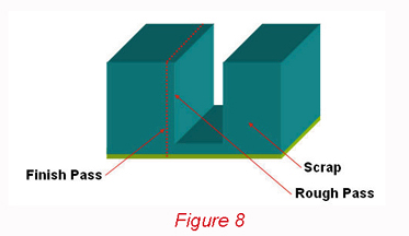 A good rule of thumb is a maximum of twice
the cutter diameter per depth of cut. A favorite programming
method is to use multiple depths of cut when cutter
breakage is an issue and then to take a final clean-up pass
of .015” for the entire material thickness. (see Figure 8)
This gives a premium edge finish while preventing broken
tools in the smaller diameters. It is a common concern
that taking finish passes in small parts will cause the parts
to move once they have been cut away from the scrap,
particularly in intricate parts like letters. The best solution
is to use the multiple depth pass/single finish pass method
described above, but to not cut through the paper masking
on the bottom side of parts. This allows the vacuum to
continue holding the parts, while the .015” finish pass will
not typically tear the parts off of the masking.
While much of the information presented above was in
the form of Rules of Thumb, it is essential that only the
proper cutting tools and cutting parameters be used when
machining acrylics. The information presented here is a
broad overview of information regarding routing of acrylics.
The best source of detailed information is typically the tooling
manufacturer’s recommendations either through published
sources or their Technical Services Departments.
A good rule of thumb is a maximum of twice
the cutter diameter per depth of cut. A favorite programming
method is to use multiple depths of cut when cutter
breakage is an issue and then to take a final clean-up pass
of .015” for the entire material thickness. (see Figure 8)
This gives a premium edge finish while preventing broken
tools in the smaller diameters. It is a common concern
that taking finish passes in small parts will cause the parts
to move once they have been cut away from the scrap,
particularly in intricate parts like letters. The best solution
is to use the multiple depth pass/single finish pass method
described above, but to not cut through the paper masking
on the bottom side of parts. This allows the vacuum to
continue holding the parts, while the .015” finish pass will
not typically tear the parts off of the masking.
While much of the information presented above was in
the form of Rules of Thumb, it is essential that only the
proper cutting tools and cutting parameters be used when
machining acrylics. The information presented here is a
broad overview of information regarding routing of acrylics.
The best source of detailed information is typically the tooling
manufacturer’s recommendations either through published
sources or their Technical Services Departments.
Van Niser is Director of Plastic Application Engineering
at Onsrud Cutter. Readers are invited to send questions to
Van Niser at Onsrud Cutter, 800 Liberty Drive,
Libertyville, IL 60048, E-mail: vniser@onsrud.com.
For more information, click on the author biography at the top of this page.
|