|
ROUTING: Fixturing & Routing Plastics With CNC Tooling
After proper bit selection, the most essential factors
in successful routing of plastics are optimum
programming techniques, solid fixturing and fast
speeds and feeds.
With the ever-increasing use of routers to machine
plastics, there has been a leap forward in the design of
tooling to produce high-quality finishes on a variety of
products. High-speed steel (HSS), carbide-tipped, solid
carbide and diamond tools have been manufactured in a
variety of geometries and sizes to rout most plastics.
Once an optimal bit is selected, however, achieving good
productivity still involves determining appropriate programming
methods, part fixturing and proper spindle
speeds and feed rates.
Programming Techniques
The goals of routing plastics are
high-quality finishes at fast feed
rates. Many programming techniques
will work well in the plastics
industry. The primary consideration
in plastics routing is the ability
to cut chips without them
rewelding themselves to the finished
surface. In softer plastics,
this can occur frequently and lead
to a poor edge finish. Preventing
this rewelding and producing a
smooth edge finish while attaining
fast feed rates is the secret to productive
plastics machining.
The key to preventing chips from
rewelding is simple — keep them
cool. The easiest method is fast feed
rates. But due to programming limitations,
this is not always practical.
Most routers have acceleration,
deceleration and curve speed limitations
when cutting radii and corners.
Dead stops should be avoided
whenever possible. When cutting
outside corners, the router will stop
and dwell while changing directions.
At 18,000 rpm, a double edge tool will contact the part 600 times per
second and generate significant
amounts of heat. 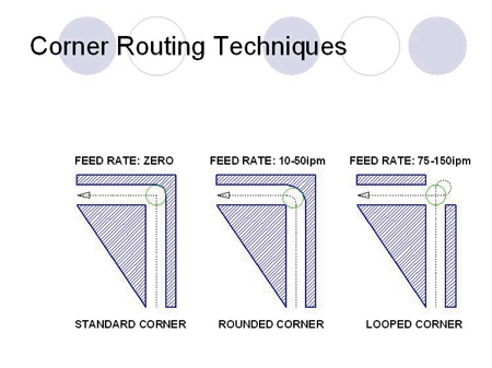
This heat will not
only increase the instances of chip
rewelding, but will also decrease
the tool life and raise tooling
costs. A solution to tool dwelling is
to utilize “exit ramp” programming.
By programming corners as
outside loops, the tool is not
allowed to dwell and you can
achieve a square corner.
A second case when router bits
dwell is during the initial plunge of an inside cut. As the bit
is boring, it is continually re-contacting the cut surface, and
unless the bit is a spiral or has shear, the chips are not
being evacuated. This generates heat both from the rubbing
and from the fact that the bit must do extra work
recutting chips that remain in the hole. “Ramp in” cutting
can eliminate this effect by gradually plunging the bit (Zaxis
movement) as it begins its forward travel (Y- or X-axis
movement). If needed, the bit can travel backward after the
full depth of plunge to eliminate the cut ramp. The dwell
time involved with this reverse traverse is significantly less
than that involving a straight plunge and rout operation.
A final suggestion to reduce dwell time: when boring a
dedicated hole, actually rout the hole. Using a small diameter
bit, ramp into the hole in a circular
fashion and use a routing
action to cut the hole to size. This
allows you to hold tight tolerances
and prevents the occasional blowout
on the underside of a hole
when the plug is ejected.
While ramp programming to
remove dwell time may seem to
increase the routing path, the higher
production feed rates that are
attainable, along with the increased
tool life, should make the operation
economically attractive.
Assuming there are no software restrictions, if chip
rewelding is still a problem after removing dwell points,
move from HSS tooling to solid carbide as this will enable
an increase in feed rate. Increasing feed rates can reduce
the instances of chip rewelding.
Sometimes because of part configuration, thickness, or
composition, it is difficult to produce a high-quality edge
on a finished part. From a programming standpoint, there
are techniques that can be used to increase finished-edge
quality. A rough cut and finishing pass combination works
well on many thicker plastics. By leaving approximately
0.080 inch on the edge with a roughing tool, a finishing
tool can clean up the edge and have enough material to cut, so that the tool remains stable and does not begin to
chatter. An added benefit is that the number of pieces
produced per finishing tool is greatly increased while the
more durable roughing tool is the one subjected to
increased wear.
When cutting nested or mirrored parts with a single
pass, operators may notice a decrease in surface finish on
one of the exposed edges. Frequently, surface finish can
change depending on whether the tool is presented to the
material in a climb-cut configuration or a conventional cut
configuration. Generally, conventional cutting yields a better
edge, unless a finish pass is used, in which case the
second pass can be a climb cut. If nested part cutting
does yield problems, the cut can
be accomplished in two passes
with the smaller diameter tool.
The first pass will finish cut one
side and then the tool travel will
be reversed and the remaining
side will be finish cut. 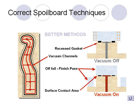
Finally, when cutting laminated
plastics or products that have an
abrasive layer, tool oscillation can
greatly increase tool life. Materials
such as plastic laminated with aluminum
can cause a severe wear
line on both carbide and highspeed
steel. By oscillating the tool vertically (Z-axis) during
the cut, this wear can be spread over a larger area and
allow the bit to continue cutting before it is dull.
Fixturing
Quality production demands quality material, quality
tooling and quality fixturing. Fixturing must be solid and
reliable. Anything else will ultimately lead to poor edge
finish and reduced tool life or broken tools. That said,
there are specific techniques and configurations that can
lead to a more efficient and practical hold-down system.
Vacuum hold-down is the most prevalent method in the
CNC industry today and it is important to get the most out
of the system. First of all, a
piece of MDF with weatherstripping
tape and a few holes
drilled in it is not adequate.
Vacuum hold-down with a spoilboard
is capable of extremely
rigid part fixturing but only if
utilized correctly.
Using the router to create a
grid connecting the vacuum
ports allows the vacuum to
reach all edges of the part to
be machined. This will increase
the holding power of the vacuum
system and allow better
edge finishes due to a rigid holding
configuration. Using proper gasketing
tape in an over-sized channel will also
increase the lifetime of the spoilboard.
If the tape used is not for gasketing
applications and has “memory,”
it will not expand back to its original
state after repeated compressions
and the vacuum system may
begin to bleed off. Additionally, if the
channel is not oversized, when the
tape is compressed by the part it will
have nowhere to go. This may prevent
the part from contacting the vacuum
surface and allow vibration to occur.
Other improvements for spoilboards
include building dedicated
boards for particular parts. One
example involves cutting parts that
have small scrap pieces. When the finished
part is cut, excess material (outside
corners, plugs from boring, etc.)
can become missiles if they are too
small to be held effectively by the vacuum
pressure. As they chatter on the
table they can contact the router bit
and either cause damage to the bit or
be “shot” off the table. To eliminate
this problem, build up the spoilboard
in certain areas and seal the edges so
that the part is actually being held on
the top of a pedestal or plateau. In this configuration, the
excess material will fall to the main spoilboard when cut
and be clear of the cutting tool.
Dedicated spoilboards can also be useful when material
composition demands a downcut spiral or shear tool.
Soft plastics require that the chips be cleared quickly and
aggressively. When using a downcut bit without a raised
spoilboard, the chips are not able to clear out of the cut.
By routing channels in the spoilboard below the areas to
be cut, it is possible to give the chips a place to clear.
If these configurations still do not provide sufficient
holding force and safety, the parts can be held with riveted
tabs or screwed into the spoilboard through the center
of scrap portions. This is the last resort due to the fact
that set-up time per piece is increased and throughput is
reduced.
Speeds And Feeds
If the part to be machined is fixtured securely and the
correct tool has been selected for the material, spindle
speed and feed rate will be the determining factors on the
finished quality of the part. Speeds and feeds can vary
greatly depending on router horsepower, tooling and part
composition. However, it is possible to make an educated
guess at the correct ratios and to then fine-tune the finish. 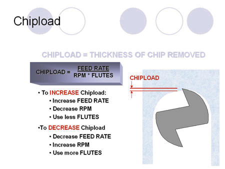
The defining ratio of speed and feed combinations is
“chipload.” Chipload is the thickness of the chip that is
removed by a cutting edge per revolution.
In effect, increasing the chipload will cause a larger chip
to be removed. The larger the chip removed, the more
heat that is removed with it and the longer the tool life.
The primary means of increasing chipload is to increase
the feed rate as this has the added benefit of increasing
the parts produced per hour.
Chipload can also be increased by lowering spindle
speed if feed rate is already at a maximum. Decreased
chipload means the number of times that a cutting edge
is presented to the workpiece is increased. Every router
bit edge has only a finite number of times it can be used
to cut before it is considered dull. Therefore, the highest
chipload that will produce an acceptable finish should be
used to prolong cutter life.
Since CNC operators do not think in terms of chipload,
but rather speeds and feeds, it is useful to have some
“rules of thumb” when determining rates. For the following
examples, a spindle speed of 18,000 rpm is assumed. For
soft plastics, solid carbide spiral tools that have geometry
specifically for cutting that type of plastic can be run at
approximately 300 inches per minute (ipm). Solid carbide
“O” flutes should also be run that fast in order to clear the
chips. If finish begins to degrade, the spindle speed can be
increased in order to maintain the same production rate.
High-speed steel “O” flute tools require slower feed rates
in order to prevent the bit from deflecting and causing
chatter or knife marks.
Harder plastics work well with low-helix tools that have
been designed to break the plastic chips away cleanly.
These tools can be run at around 300 ipm. Double-edged
“V” flute tools can run anywhere from 125 ipm to 250
ipm, depending on style and bit composition, and also
produce an excellent finish. It is important to understand
that in all cases, whether routing hard or soft plastics,
chips (not dust) must be made. Large chips will not reweld
to a cut surface and will prolong the life of the tool. If the
cut waste that is produced is dust, that means the chips
have been recut numerous times or the chipload is too
low. The tool life will suffer, as well as the edge finish.
Fiber-reinforced plastics are different from other types
of plastics in that it is very difficult to determine the type
of chip being produced. Because of the structure of materials
such as fiberglass, aramid and carbon fiber compounds,
chips are not formed during the cutting process.
In these instances, it is best to run the bit as fast as possible.
The cooler the bit is when finished, the longer the
tool life can be expected of the bit.
If, despite adjusting speeds and feeds, the best cut still
produces a hot tool or causes occasional chip rewelding,
forced air can be used to evacuate the chips. First, make
sure the dust collection system is operating efficiently.
Then, use air forced through a directional nozzle to clear
the chips. Additionally, several companies manufacture
Venturi effect nozzles, which can drop the temperature of
the air charge and provide additional cooling as well as
chip evacuation.
With the ever increasing formulations of plastic in the
marketplace, there is going to be a continuing need for
high-quality machining and finishing work. After proper bit
selection, the most essential items to successful routing of
these materials involve optimum programming techniques,
solid fixturing, and fast speeds and feeds. Be sure
as much emphasis is placed on the tooling, fixturing and
programming as is placed on the CNC equipment that is
expected to utilize it.
Van Niser is Director of Plastic Application Engineering
at Onsrud Cutter. Readers are invited to send questions to
Van Niser at Onsrud Cutter, 800 Liberty Drive,
Libertyville, IL 60048, E-mail: vniser@onsrud.com.
For more information, click on the Author Biography link at the top of this page.
|