|
ROUTING: Major Considerations in the Routing of Plastic
Before the process of routing or machining plastic,
the user must evaluate the capabilities inherent
to the operation.
Capability
The first consideration is in the area of machinery, which
can vary widely in the world of plastic fabrication.
Machines of choice include: air and electric routers, pin
routers and CNC machinery. These types of machines are
prevalent in sheet fabrication, thermoforming and rotational
molding operations throughout the plastic industry.
Air, electric and pin routers fall into the categories of
hand fed applications and present an entirely different set
of circumstances than a CNC application. Since these
machines are heavily influenced by the skill of the individual
operators, the tooling material of choice should be
high speed steel or carbide tipped with a steel shank.
These tool materials are more forgiving in a hand fed
application and less likely to fail than solid carbide, which
thrive best in the controlled environment of CNC.
Within hand fed operations, one of the more prevalent
machines is the air router. The air router has some characteristics
which have a direct effect on the tooling choices.
The diagram below, (Figure 1-Air Router Assembly
Diagram) illustrates that the air router has a nose or support
bearing, a guard and a guide bushing. All these features
have important functions but they necessitate the
use of router tooling specific to the air router.
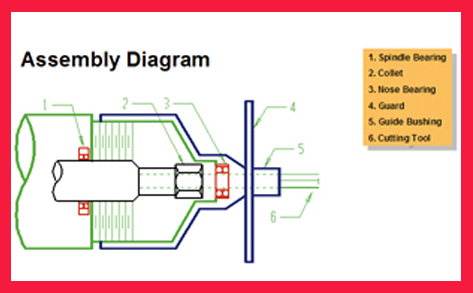 These tools
must be manufactured with long enough overall length to
bottom out in the collet and extend beyond the guide
bushing while making contact with the work piece. Also,
the tools must be slightly undersized along the entire
length of the tool to pass smoothly through the support or
nose bearing. The forcing of on size tooling through the
support bearing alters the bearing and negates the function
of this critical mechanism, which adversely affects the
concentricity of the cutting tool. Consequently, it is important
to incorporate tooling properly toleranced for air
routers.
These tools
must be manufactured with long enough overall length to
bottom out in the collet and extend beyond the guide
bushing while making contact with the work piece. Also,
the tools must be slightly undersized along the entire
length of the tool to pass smoothly through the support or
nose bearing. The forcing of on size tooling through the
support bearing alters the bearing and negates the function
of this critical mechanism, which adversely affects the
concentricity of the cutting tool. Consequently, it is important
to incorporate tooling properly toleranced for air
routers.
CNC routers are extremely popular
among plastic fabricators with 3-axis
and 5-axis machines fulfilling a variety
of needs. Generally speaking, flat sheet
fabricators utilize 3-axis, while thermoformers
with a need to attack multishaped
parts at an angle, account for
most of the 5-axis machines. Solid carbide
is the tooling material widely utilized
because of it’s toughness and the
longevity of the cutting edge when chip
load is properly maximized.
 Solid carbide
router tools are available in a
broad range of geometries and styles.
Sheet fabricators usually prefer upcut
spirals to aid in the extraction of
potentially soft plastic chips. On the
other hand, thermoformers with
formed fixtures tend to use straight
edge tooling, which has a neutral effect
on the part. Downcut spirals can be
utilized in some 5-axis applications but
the fixturing must be such that the
chips fall away from the part. If the
chips cannot fall freely from the part,
recutting of plastic chips can cause
welding to occur which is detrimental
to the part and the router tool.
Solid carbide
router tools are available in a
broad range of geometries and styles.
Sheet fabricators usually prefer upcut
spirals to aid in the extraction of
potentially soft plastic chips. On the
other hand, thermoformers with
formed fixtures tend to use straight
edge tooling, which has a neutral effect
on the part. Downcut spirals can be
utilized in some 5-axis applications but
the fixturing must be such that the
chips fall away from the part. If the
chips cannot fall freely from the part,
recutting of plastic chips can cause
welding to occur which is detrimental
to the part and the router tool.
Regardless of the type of machinery utilized, the ability
to properly hold the part is critical. The three methods
associated with part holddown include: mechanical i.e.;
clamps, dedicated and flow-through spoilboard systems.
Dedicated and flow-through are the two most prevalent
systems in the area of CNC routing. Flow-through has
become the most popular because of the ease of setup
but there is no question that the best approach to solidly
holding parts is a properly built dedicated spoilboard.
The savings in reworked parts, scrapped parts
and overall cycle time is well worth the
effort.
Lastly in terms of capability and machinery,
the machinery is only as good as its
maintenance schedule. The critical maintenance
on a router as it relates cutting tools
is the collet. Concentricity of the router tool
can only be accomplished with a clean and
well-maintained collet system.
Tool Selection
Once capability has been determined in
terms of properly maintained machinery
and rigidity of part to be machined, tool
selection becomes paramount.
 Router
tools for plastic cutting are application and
material specific. In almost all cases, one
cutting tool cannot be utilized across a
variety of plastic material. Router
tools for plastic cutting are application and
material specific. In almost all cases, one
cutting tool cannot be utilized across a
variety of plastic material.
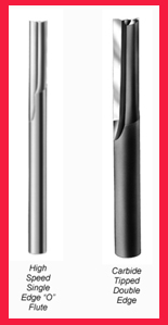
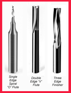
Generally speaking, plastic can be categorized
as either hard or soft plastic. Soft plastic will curl
a chip and hard plastic tends to produce a splintered
wedge, which is actually broken off in the machining
process. The use of “O” flute tools in straight and spiral
configuration with high rake angles and low clearance will
aid in eliminating the knife marks associated with soft
plastic. Hard plastic is best routed with
double edge “V” flutes, spiral “O” flutes
with hard plastic geometry, or two and
three edge finishers. These tools along with
the proper chip load produce a crater free
finish. Cratering in hard plastic occurs
when the shear strength of the material is
exceeded in the routing process.
The aforementioned tooling suggestions
are accurate starting points but extremely
general in nature. For specific tooling recommendations
by plastic material, log onto
the Internet at www.plasticrouting.com.
Once tool selection has been finalized,
chip load becomes a critical consideration.
Chip load or the actual thickness of
the chip is a function of the spindle speed
(RPM), the travel speed of the cutting
tool (IPM) and the number of cutting
edges of the tool. In plastic, there is a
very narrow range of chip load to maximize
finish and cycle time. Since finish seems to be one
of the most important factors in machining plastic, the
range falls between .004 and .012. However, finish is
always a personal decision and some applications may
warrant a larger chip load at the expense of finish to
increase productivity. In other words, do not be limited
by the recommended range but
use it as a guide.
Conclusion
Plastic material is showing up in
routing and machine shops everywhere.
It is a new material for many
and it cannot be machined with the
same tools or same methods used
for metal or wood. The systematic
process of considering machine
capability, tool selection and a functional
chip load, which is the outcome
of feed and speed, is critical.
Once this has been accomplished,
the user is prepared to enter the
world of machining plastic with confidence.
For more on spoilboards and
proper collet maintenance, see the Van Niser article archive on the left side of this page.
For more information, click on the Author Biography link at the top of this page.
|