|
ROUTING: Routing Composites
Why are composites such
difficult materials to cut? What
can be used to cut them in a
cost-effective method? Can
coatings help tool life? These
are several of the most asked
questions today. This article will
explain some of the major factors
and how to address them.
In this discussion of cutting tools for composites, in
particular small diameter round rotating tools, it is
necessary to define in
general terms and conditions
how composites
are processed into parts.
A composite is a material
composed of reinforcing
fibers held into a finished
form by a cured
resin or matrix. The normal
fibers are made of
graphite, fiberglass and
aramid. By combining
both, a new part is made
that is stronger and more durable than the components
themselves.
The terms Carbon and Graphite are used interchangeably
in today’s conversations to describe Graphite composite
parts, even though
Graphite is Carbon fiber
processed to a higher strength.
In this discussion they will be
considered the same because
they are cut with the same
types of tools.
The fibers themselves can be
in the forms of: small pieces
(chopped), a mesh or scrim,
fibers in a unified direction, or
woven cloth and a mix of any or
all of the above. To further
expand things, the use of two or more types of fibers may
be used in the above combinations. The finished parts have many layers of these materials because layers are very
thin. A cure layer of composites is approximately .008”
thick. These means that a part 1/8” (.125”) thick will have
15 or more layers. So we have a very strong base material
that is highly concentrated and uniformly layered. All of
these increase the part’s strength dramatically.
The supporting matrixes are usually some type of catalyst/
resin forms. They are thermoset types and they are
processed in two ways: first, those that are cured at room
temperatures and pressures (most as resins introduced as
a wet-layup), and, second, those that are cured at elevated
temperatures and pressures (most as resins already
pre-impregnated into material). The higher temperatures
and higher pressures increase the composite’s strength
greatly. In most cases the pressures are applied by the use
of a pressurized oven (autoclave) or by a press.
These parts are further divided into divisions: solid and
filled. The different types of composites in either unified
tape or woven goods are not segregated because both,
after curing into a finished part, are uniform and consistent,
and therefore shear in much the same manner.
These can occur in the same parts, for example aircraft
interior panels, like overhead storage doors, can have a
solid edge to attach the hinges and the center is filled with
honeycomb core. This combination of systems allows for a
lightweight, strong panel with a strong edge.
One of the major characteristics of these two processes
is fiber to resin content ratio. In room temperature/pressure
parts there is more resin than fibers, 60%/40% is
normal. In the elevated temperature/pressure types the
ratio is closer to 40%/60%, resin to fiber. Since the fibers
are the highest strength values and there are more of
them in this type, it presents a challenge in tool designs
and materials. As stated previously, these composites are
very strong. The fibers are between 300 and 500 kpsi
tensile strength for fiberglass and aramid. The graphite
fibers range from 350 to 900+ kpsi in some forms, most
about 500 kpsi.
The first of these systems lend themselves to lower
strength applications such as boats, auto body panels,
spas, etc.
The second is for the higher strength needs of parts for
aircraft interior panels, aircraft structural parts, racecar
frames/bodies, circuit boards, electrical insulators, etc.
These are the parts that are addressed in this article. Recap high strength composite parts
characteristics:
-
High strength fibers
-
Strong resins
-
Combined and cured together in densely
packed parts
-
Can be combined with lighter core materials
-
Many uniform layers
Modern day cutting tools materials
for composites are Solid Carbide (SC)
(Uncoated and Coated), Polycrystalline
Diamond (PCD) (brazed or mounted to
a body), and Natural Diamonds (DG)
(in grit form, bonded to the tool body
by electro-plated or fire-brazed methods).
They are also offered in the
forms of straight flutes, spirals, burrs
and combinations of the all the above.
The basic grade for this carbide is C-2.
The SC tools in most applications
offer the best cost-effective tool material
so this article will address its use
in these operations.
Solid carbide itself is a composite of
Tungsten Carbide wear particles and
Cobalt binders. The solid carbides in
micrograin or submicron grain sizes
used for tools today have a traverse
rupture strength of 350 to 450 kpsi.
These values are close to the tensile
strength of the fibers themselves.
To
make these materials cut the fibers,
flute geometry is ground in the body
to introduce a shearing action. The
modern grinding machines can also
produce more complex, uniform and
repeatable geometries.
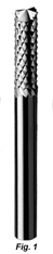
For many years the fiberglass routers (FGR), better known as burrs, have been used in the cutting of composites (See Figure 1).
An examination of the geometry of the FGR’s
will show they are comprised of up and down
spiral geometry. These spirals generate many
cutting points that shear the fiber in the composites.
The resins are carried along with the
fiber chips. These tools have an uneven count of
spirals, up verses down, to make the points
overlap so that they do not make grooves in the
finished part edge. These tools have performed
very well in the past. They act like chip-breakers
and reduce the amount of cutting forces needed
to cut the fibers. There are improvements on this
design by:
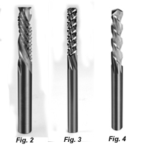
Un-ruffer style combining a burr geometry
with up/down compression spiral flutes to act
as a finishing cut on the fibers (See Figure 2).
CG style tools for the up/down shearing
actions combined with a strong flute geometry
for fiberglass and graphite composites (See Figure 3).
FMR style tools for the up/down forces combined
increased shearing action of the flutes required for cutting
the more pliable aramid composites (See Figure 4).
The Up/Down flutes of the tools sends the force toward
the center of the parts, not to the surfaces. This action
reduces the delamination or separation of the plies of the
composites. The modifications
of flute edges
and the chip-breaker
action of the opposing
flute make the shearing
action work to cut
the fiber easier and to
clear the chips from
the cut.
The Un-ruffer is used
in sandwich panel
applications where the
thin skin on the outside
of the panels supports
a core of lighter materials.
The cores can be
honeycomb core, foam
or balsa wood. The
burr portion of the
tools cut small chips from the surfaces and the core with the
up/down flutes make a finishing pass on the skins. This combination
greatly reduces the risk of delaminating the skins.
It should be noted that the honeycomb core surface will still
be rough in some areas because of its thin wall. It will fold
over rather than shear in a condition known as flagging.
The CG tools are a highly modified version of the
up/down compression fluted spirals that address the high strength of the fiberglass and graphite fibers. As in the
above examples, the cutting forces are directed to the
center of the part. The reason they are an improvement
over the FGR’s is because of the higher strengths of the
newer carbides available and grinding equipment. This is
higher strength, because of the more uniform grain structure
than the previous versions of C-2 carbide. An additional
factor is the more uniform mix of the individual
components of the carbide itself. Solid carbide processes
and equipment are highly controlled today, adding to the
uniformity of the product.
The FMR tools follow the CG design in the up/down
geometry. The fibers of the aramid parts are weaker than
the graphite fibers, so the flutes need not be as strong.
This allows for adjustments to be made to the sharpness
of the flutes by rebalancing the flute’s rake angles to
cross-sectional area ratios. Since the chips are usually
larger than the fiberglass and graphite chips, additional
adjustments to the helix angles can be made for the chip
evacuations.
The use of coatings is not a panacea. Coatings can be
used to increase surface hardness, protect the carbide
matrix, and/or add lubricity to the flute surface. The
process adds a covering to the cutting edge creating a
small radius which reduces its sharpness. This can
increase the amount of force required for shearing the
fibers.
As to protecting the cobalt binders, the cement holding
the carbide together, most coatings do an excellent job.
By coating the tool surface, the microscopic grooves created
by the grinding process are flattened slightly and the
coating is slicker than the carbide allowing the chips to
flow easier across the face. This can reduce the amount of
force required to cut the composites.
As to feed and speed parameters for composite materials
there some basic rules. Consider the tools to be a single
edge cutter. In theory these tools will have one edge
on a larger cutting diameter than all the rest. It will lead
the others, microscopically, in the cutting action. This will
also allow easier calculations of the chip loads by dividing
the feed rate by the spindle speed, i.e. Chip Load = Feed
Rate (IPM) / Spindle Speed (RPM).
Solid carbide tools in one of the four styles are one of
the most cost-effective methods of cutting today’s high
strength composites. The raw materials are very uniform
and have increased strength. The modern grinding equipment
produces a more accurate and consistent geometry.
This, combined with the some usage of coatings, offers the
best solutions for cutting composite panels.
For more information, click on the Author Biography link at the top of this page.
|