|
ROUTING: The Importance Of Spoilboards
The emphasis today in the fabricating and machining
of plastics is CNC — or computer numerical
controlled machines. These high spindle speed,
high feed rate machines accomplish a tremendous
amount of work in cycle times, which enhance productivity
and profitability. A great deal of time is devoted to the
selection of such machines and the appropriate tooling
and accessories, but the area of spoilboard methodology
is given less consideration. Without proper investment of
time in this critical area, the holding of parts to accomplish
maximum productivity becomes challenging at best.
Types of Spoilboards
The dedicated or discreet spoilboard
system has traditionally been
utilized over the years to machine
individual parts that are held by a
gasketed vacuum system. Unfortunately,
many times the process of adequately
constructing these spoilboards
has been ignored in the interest
of time. The use of a piece of MDF
or particleboard with holes drilled
inside an area encapsulated by selfstick
weather stripping does not meet
the demands placed on the parts in a
high-speed application. Consequently,
it is imperative to follow certain criteria
when building spoilboards to maximize
the part hold-down procedure.
First, the selection of gasketing
material is foremost in the process of
building substantial dedicated spoilboards.
This material should be quality
closed cell foam, which has the
ability to return to its original configuration
repeatedly under rigorous
machining conditions. Self-stick weather
stripping, which is open cell construction,
does not possess such
memory characteristics and should
never be utilized. The gasketing
material represents the perimeter of
the part configuration and must have
the resiliency and durability to maximize part rigidity and
reduce vibration. A good technical source for gasket material
and usage is at www.allstaradhesives.com.
After the proper gasketing material is selected, a channel
should be routed into the spoilboard to establish the outside
perimeter of the part and as a recessed area for application
of the gasketing tape. This process allows the part to
be solidly held to the table surface, and prolongs the life of
tape. The source of vacuum is port holes drilled in the interior
of the gasket perimeter. In order to generate a larger
vacuum surface area the holes should be connected to a
groove routed just inside the gasket perimeter. This provides
an arterial flow to the outermost edge of the part and
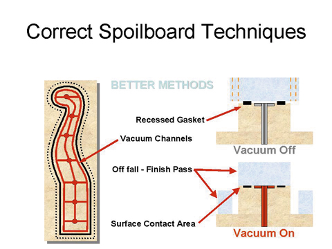 substantially increases rigidity (Figure 1). Furthermore, the
actual spoilboard is often significantly impacted when constructed
of double-sided melamine board to reduce the
leakage of vacuum associated with raw board materials.
substantially increases rigidity (Figure 1). Furthermore, the
actual spoilboard is often significantly impacted when constructed
of double-sided melamine board to reduce the
leakage of vacuum associated with raw board materials.
The second type of spoilboard is universal vacuum, which
is also referred to as high volume, flow through or suck
through vacuum. This method distributes volume of vacuum
throughout the entire surface of low or medium density
spoilboard, and has gained popularity because of minimal
setup time. The process is utilized to cut parts from whole
sheets of raw materials, and is particularly effective on larger
parts where part movement is not a major concern.
However, smaller parts can become problematic with this
spoilboard approach and other techniques should be
employed to avoid part movement. Tab cutting and skin cutting
techniques are especially effective in dealing with small
parts. This involves leaving a tab or a thin layer of material
on the bottom of the part to hold them together. The tab or
skin portion is then removed in a secondary operation. This
process is slightly more time consuming, but the final
results are quality edges and less scrapped parts caused by
movement during the machining process.
Since the universal vacuum approach involves high flow
without the inherent benefits of dedicated spoilboards,
the opportunity for leaks and subsequent part movement
is always present. In order to minimize those kinds of
problems, additional techniques can be applied. Rubberized
paint can be applied to seal spoilboard edges.
Smaller diameter tools will minimize cutting pressure and
reduce larger open spaces on the cutting area.
 Scrap
parts or plastic sheet can be used to cover open, unused
areas of the spoilboard when smaller than whole sheet
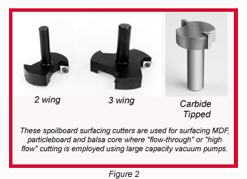
raw material is utilized. Furthermore, the spoilboard
should be surfaced with a large diameter spoilboard surfacing
cutter. This process should be done initially to both
sides of the spoilboard before actual machining of parts to
increase porosity and ensure the surface of the board is
flat. The cutter is continually used to maintain those two
parameters and eliminate rout lines caused by the cutting
tool during the machining process (Figure 2).
Scrap
parts or plastic sheet can be used to cover open, unused
areas of the spoilboard when smaller than whole sheet
raw material is utilized. Furthermore, the spoilboard
should be surfaced with a large diameter spoilboard surfacing
cutter. This process should be done initially to both
sides of the spoilboard before actual machining of parts to
increase porosity and ensure the surface of the board is
flat. The cutter is continually used to maintain those two
parameters and eliminate rout lines caused by the cutting
tool during the machining process (Figure 2).
Criteria for Vacuum System
In addition to actual spoilboard, the vacuum system
should be constantly evaluated to guarantee optimum
performance. Rating this system should include the following
criteria:
Does the pump have enough suction? -
400 cfm w/15in Hg for flow-through systems.
- 80 cfm w/25in Hg for dedicated systems.
Are supply lines large enough? -
3 inch diameter minimum for flow-through systems, 4
to 5 inches recommended.
-
3/8 inch diameter for dedicated systems, 1/2 inch recommended.
Are there enough vacuum sources?
How many bends are in the supply lines?
Are potential vacuum leak areas and unused areas
sealed?
Regardless of which spoilboard application is utilized, it
is imperative to follow good construction and enhancement
techniques to ensure parts are held solidly. In the
world of high-speed machining in plastics, it is the only
method to produce quality parts on a consistent basis.
For more information, click on the Author Biography link at the top of this page.
|