|
ROUTING: Removing The Heat From Cutting Tools
Incorrect feed rates, plunging speeds and
spiral directions can cause excessive heat to
the cutting tool, resulting in a poor cut.
Heat is the enemy of cutting tool life. Cutting tools,
including router bits, are made from materials
that are adversely affected by heat. An understanding
of the mechanisms behind heat generation and
how to eliminate or minimize heat
build-up in routing applications can
lead to longer tool life and reduced
tooling costs.
Heat Generation In
Cutting Tools
There are two main problems associated
with heat generation during
routing. The first problem is its
adverse affect on cutting tool structure.
The second problem is melting
of the product.
Melting of the product can cause
poor surface finish from chip
rewelding. It can load the flute of
the tool and cause catastrophic
failure or breakage. It can also
cause a chip to wrap on the cutting
tool. Since all of these problems
can produce unacceptable parts,
the best prevention is to keep the
tool cool.
There are many causes of heat
build-up in a cutting tool. The main
cause is having too high of a spindle
RPM compared to the rate of material
feed. In other words, the cutting
tool is not cutting a reasonable chip,
but rather rubbing the material. The
rubbing causes friction, which causes
heat, which can lead to structural changes in the cutting
tool and the material being cut.
The following is a partial list of some of the causes of heat buildup in cutting tools: -
Improper tool material for the
application (HSS vs. carbide)
- The feed rates for the plastic are
too low
-
The spindle speed for the tool is
too high
-
Stopping and/or dwelling in the
cut path
-
Excessive or slow plunging
- Incorrect spiral direction (down
cut vs. upcut)
-
Feeding the tool in the wrong
direction (conventional vs. climb
cut)
-
Running the spindle in the wrong
direction
-
Plunging the tool into the part
beyond the cutting edge
- Using the tools after they become
dull
-
Running into the steel hold-down
clamps
-
The chip load on the finish pass is
too light
-
The plastic material requires multiple
tool passes without a cooling
period
There are many causes for heat
buildup in a cutting tool. When using
router bits in any type of router,
after you finish the operation, turn
off the power and touch the router
bit. If it is hot to the touch, you have
not run the bit correctly and tool life
has been degraded.
Minimization Of Heat
Buildup
In order to minimize or eliminate
heat buildup on router bits, the trick
is to feed the material past the router
bit as fast as possible. For example,
for routing plastics at a spindle speed
of 18,000 RPM, the feed rate should
be between 200 inches per minute
and 400 inches per minute. If you
cannot feed that fast, slow down the
RPM of the spindle.
When cutting plastics, you want to
develop a distinct chip, not powder.
The larger the chip, the more heat is
carried away from the tool. The two
limiting factors of feed rate are spindle
horsepower and deterioration of
the quality of the cut. If this happens,
the feed rate needs to be slowed
down. Just remember, the slower the
feed speed, the more heat builds up
in the router bit and the shorter the
tool life becomes.
The other considerations in maximizing
tool life revolve around maintaining
your router and collets in
good condition by proper fixturing,
proper tool selection, using sharp
tools and controlling the machining
process. If all of these considerations
are addressed, and you feed at a
reasonable rate, you will get the
maximum life out of your router bits.
Real World Examples
In the normal world of routing,
router bits perform two functions
when cutting parts. First, they
remove the excess material around
the part’s perimeter. Second, they
smooth the part’s edge. Sometimes
this can be accomplished in one
pass, although there are times when
a roughing/finishing combination is
needed. Following are two real-world
problems associated with heat generation
and the solutions used to
solve them:
-
Problem:-
The first example required a
roughing and finishing pass to produce
a finished part. Acrylic was
being cut for an aircraft window
application and the parts needed an
excessive amount of clean-up work
because of tiny cracks made during
the routing.
 The cracks would not
become visible until the polishing
operation.
The cracks would not
become visible until the polishing
operation.
The single edge “O” flute solid carbide
tool used on the CNC router
could not remove all the heat with
the chips and was causing structural
deformities within the acrylic.
-
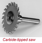
Solution:
The solution was to use a carbide-tipped saw with a negative
5-degree rake. The part was cut within 1/16” of finish
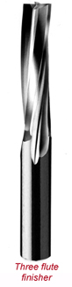
size. A solid carbide three-flute finishing tool was then
used on the second pass in a climb out
direction. The resulting finish eliminated
two clean-up operations and there
were no more cracks.
-
Problem:
-
Another example of two passes
involved an electronic parts washer.
The washer parts were made from a
high-density polypropylene about 2
inches thick.
 The part was being cut in
two passes with a solid carbide 1/2-
inch diameter “O” flute with a 1-inch
cutting edge length. The edge of the
finished part would have a line showing
where the first pass stopped and the
second pass would leave chips welded
to the part.
The part was being cut in
two passes with a solid carbide 1/2-
inch diameter “O” flute with a 1-inch
cutting edge length. The edge of the
finished part would have a line showing
where the first pass stopped and the
second pass would leave chips welded
to the part.
-
Solution:
-
The solution was to use a 1/2-inch
diameter solid carbide three-flute finishing
tool with a 2 1/8-inch cutting
edge length. This tool also required
two passes, 1 inch deep and 2 1/16
inches deep. The normal depth a tool can cut is two
times its cutting diameter, in this case 1/2 inch by 2
equals 1-inch depth. To eliminate the line made during
the first pass, the part was cut 0.04-inch oversized. Then
the second pass was made at the finished size. This
allowed the tool’s cutting edge to cut the full surface and
eliminate the line.
This second pass by the spiral cutter would lift the
chips out of the cut path and eliminate the chip welding
problem caused by the straight “O” flute design. An
additional benefit allowed by the spiral was an increase
in the feed rate so both passes were accomplished in the
same amount of time used in the first pass of the “O”
flute tool.
The point to remember is that heat is the enemy of tool
life and heat buildup in the tool can be removed by feeding
as fast as possible, making the largest possible chip.
Also keep in mind that your equipment must be kept in
cool conditions and the collets must be clean to be successful
in your routing manufacturing processes.
With proper tooling, fixturing and the correct speeds
and feeds, you can maximize your tool life and considerably
reduce your tooling investment.
For more information, click on the Author Biography link at the top of this page.
|