|
ROUTING: Routing With Air
Though simple in concept,
air routing is a
technologically advanced
process that has paid its
dues and is now the choice of
many manufacturers.
Pneumatic (or air) routing
has been a standard in many
shops and plants for
decades: its appeal only
seems to increase as technology
advances. Air routers are
simple machines that use
high-tech tooling to produce
parts that would be difficult
or unsafe to machine in any
other manner. They offer the
advantages of light weight,
easy-to-maneuver design, no
risk of electrical shock and
simple maintenance. Because
of these advantages, air routers are the router of choice
for many industrial hand routing applications.
Air routers are used to cut most machinable materials
used today including plastics, fiberglass or fiberglass/
wood composites used in the boat industry and aluminum
used in both the boat and aerospace industries. Their
applications include: cut-out routing through the use of a
template; trimming operations while
following a fixture; free-hand trimming
and, as technology grows, robotic
applications.
With the wide variety of materials
and applications in use and only a few
variations of the standard air router
available, fabricators must look to specialized
tooling to provide the best
solution for their cutting needs.
Tooling Requirements for
Air Routers
Router bits for air routers are specialty
tools. They look different, perform
better and, as opposed to standard
router bits, are designed specifically
for air routers.
 Air router tools
have the following notable differences:
Air router tools
have the following notable differences:
- Longer Overall Length: Air router
tools must extend out to the collet,
through the nose bushing and out of
the guard. For this reason, the tools
are typically 3 1/4” to 4 1/2” long.
- Undersized Cutting Edge Diameter
(CED): Bits must pass through a
support bushing or bearing.Because of this, the CED is typically
toleranced (-0.001/-0.008). Since
hand routing is not normally an
operation that requires high
tolerance, this is an accepted
method of protecting the cutting
edge from damage due to
contact with the bushing or
nose guard.
-
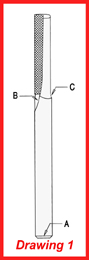
Short Flute Fadeout: (B,
Drawing 1) This adds strength
to the tool by adding material
to the place which will
have the most amount of
stress. Short
fadeouts also
allow the bushing
to rest closer
to the actual
cutting surface.
-
Smooth, Large
Radius Cam
Fadeout: (C,
Drawing 1) Similar
to the flute fadeout, this adds
strength in a weak area of the tool. The
back of the cutting edge usually doesn’t see
much action, so this added material has
only a minimal negative effect on the cutting
action while decreasing the instances of
breakage.
-
Large Chamfer: (A, Drawing 1) This prevents damage
to the bearings, bushings and collet.
Air router bits offer the same variety of cutting geometries
as standard bits. Just like standard tools, air router
bits must be selected according to the material being cut,
finish and feed desired, and operator fatigue from hand
routing. Reduced operator fatigue is normally at the
expense of cutting tool life and this must be considered
during tool selection.
Some General Recommendations For
Tool Selection
- Single flute tools are very
aggressive. Use them
where high feed rates are
needed and finish is a
secondary concern.
-
Two flute tools are much
more stable in the cut,
easier to control and
produce a better finish.
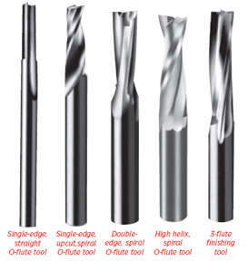
- A premium finish can be
obtained by taking two
passes: one roughing
pass with a single flute
tool and a second finishing
pass with a three- or
four-edge tool, removing
a thickness of material equal to approximately 1/4 the
diameter of the bit.
- If a spiral is desired, use a downcut. This ejects the chips
away from the operator and can help hold the part in
place.
-
When cutting thin materials use a straight tool. This will
help stabilize the material.
Operating Conditions And Maintenance
The recurring problem of inconsistent finishes, inconsistent
tool life or router bit breakage plagues all users. This
is usually blamed on the tool because it is the item that is
most visible and costly in a routing operation. But there
are a multitude of other factors which are much less visible
and more likely to cause the problems listed above.
Air Pressure
In general, routers need 90 psi and 30 cfm of dry, clean,
lubricated air supply. If the router is receiving less than 70
psi or 20 cfm, then its usable horsepower is cut in half, as
well as exhibiting a drop in its rpms.
Router bits are designed for specific rpms and do not perform
well at lower spindle speeds. Air pressure should not
drop more than 10 percent from the static pressure when the
router is turned on. Too many quick disconnects, too small a
supply line or too many users on a line can cause these pressure
problems. If air pressure drops while the spindle is under
load, it may be an indicator that the router itself is in poor
repair and may need an overhaul.
Wrong Spindle Speed
Whether it is the result of low air
pressure, a router in poor condition or
just the wrong router, spindle speed
can greatly affect the performance of
router bits. The smaller the diameter
of the tool, the higher the spindle
speed needed to cut at peak performance.
Tools with 1/8” diameters work
extremely well in some of the older
turbine-style routers that spin up to
40,000 rpm.
Coolant
If cutting some plastics or aluminum
is a problem, use coolant. Many manufacturers
keep a block of beeswax or
barsoap at each routing station. The
operator dips the bit into the block
before each cut, greatly facilitating
chip removal and producing more consistent
finished parts.
Maintenance
As with any machine, maintenance is
critical. Air routers are extremely susceptible
to particulate damage due to
their operating environments and are
notorious for not having regular maintenance and overhaul performed on them. The spindle
and nose bearings (see Drawing 2) are shielded, but not
sealed.
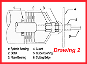 They should be replaced a minimum of every 3 to
6 months. Vanes for the spindle should be replaced every
six months. Collets should be replaced every 2 to 6
months depending on material being cut and router use.
They should be replaced a minimum of every 3 to
6 months. Vanes for the spindle should be replaced every
six months. Collets should be replaced every 2 to 6
months depending on material being cut and router use.
Spindles are usually concentric to 0.0005” from the
factory. Regular use can cause this number to increase
up to 0.002”. A damaged or dirty collet, along with a
used nose bearing, can increase this and cause runout
at the tool tip to exceed 0.010”. When there is this kind
of collaborative runout -spindle, spindle bearing, collet
and nose bearing - the tool can have runout varying
from zero to 0.010” each time it is seated and tightened
down. What this translates to is when an operator is
doing a repetitive operation, he will see one tool perform
extremely well and get a maximum number of parts,
while the next tool will be difficult to push, give a poor
finished surface and cut drastically fewer parts. The bit
is always blamed, but is rarely the actual problem.
Operator Training
Air routing, without a doubt, is very “feel” oriented. An
experienced operator can tell when a bit is dull or when
performance of the tool and bit drop. New operators will
always break more tools than an experienced counterpart.
It just takes one hit of the tool on the fixture, one
time when a single edge tool gets away from the operator,
or one plunge too fast or erratic and the cutting edge
will chip. This chip will immediately degrade performance
and cause the tool to behave differently. This starts a
chain reaction and the entire cutting edge is corrupted in
a short time. When evaluating router and router bit performance,
do not forget operator competency.
Air routing has been around for a long time and will
continue to be an extremely viable method for trimming
and/or manufacturing parts. With the correct tooling
and an excellent maintenance program, air routers
are more reliable and comfortable to use than electric
routers in abusive or repetitive applications and can be
a cost effective alternative to CNC machines.
For more information, click on the Author Biography at the top of this page.
|