|
ROUTING: The Router Way
Many wear parts
are made from
mechanical plastics.
 Common ones include
bearings, gears,
material-handling parts
and machine components
such as spacers and positioning
mounts where the
reduction of vibration is
essential.
Common ones include
bearings, gears,
material-handling parts
and machine components
such as spacers and positioning
mounts where the
reduction of vibration is
essential.
Traditionally, these types
of parts have been fabricated
from metal. But
mechanical plastics are
beginning to replace metal
because of their increased
durability, excellent
machinability and
exceptional mechanical
and electrical properties.
Common mechanical plastics
include acrylonitrile butadiene styrene (ABS),
Acetal, Delrin®, Hydex®,
nylon, polycarbonate, polyurethane
and polyethylene
terephtalate (PET).
Cutting Tool
Geometry
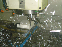
 Router bits for cutting
mechanical plastics have traditionally been run on CNC routers at high spindle
speeds and feed rates.
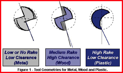
Extensive testing and
years of field experience
have shown that a tool
with a high rake and low clearance
performs exceptionally well. It
machines mechanical plastics more
productively than tools with other
geometries and imparts a finer surface
finish (Figure 1).
Router bits for cutting
mechanical plastics have traditionally been run on CNC routers at high spindle
speeds and feed rates.
Extensive testing and
years of field experience
have shown that a tool
with a high rake and low clearance
performs exceptionally well. It
machines mechanical plastics more
productively than tools with other
geometries and imparts a finer surface
finish (Figure 1).
This kind of free-cutting geometry
is rarely used by shops to machine
mechanical plastics. Most use endmills
running on CNC milling
machines.
Tool Selection
Mechanical plastics are characterized
as either soft or hard.
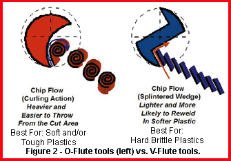 By looking
at the chip produced, a machinist can
easily determine the flexibility or
rigidity of the material being cut. Soft
plastic produces a curled chip, while
hard plastic produces a splintered
wedge. Generally, O-flute tools are
applied to soft plastic, while V-flute
tools are used with hard plastic
(Figure 2).
By looking
at the chip produced, a machinist can
easily determine the flexibility or
rigidity of the material being cut. Soft
plastic produces a curled chip, while
hard plastic produces a splintered
wedge. Generally, O-flute tools are
applied to soft plastic, while V-flute
tools are used with hard plastic
(Figure 2).
Most wear plastics are made from
soft plastic. Consequently, O-flute
tools are recommended for machining
most mechanical plastics.
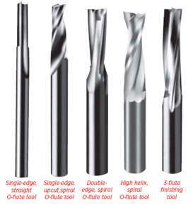
O-flute tools are manufactured in straight- or spiral-flute configurations. The choice depends
on which direction the user wants the chips to flow.
Straight tools have a neutral effect, while spiral tools can
influence the chips either upward or downward. (For purposes
of clarification, a downcut spiral is a lefthand spiral,
while an upcut spiral is a right-hand spiral.)
For the most part, routers with upcut, or right-hand,
 spirals
are applied because they effectively evacuate chips.
Downcut, or lefthand, spirals tend to recut chips, which is
not advantageous when cutting mechanical plastics where
chip welding may be a problem. However, for part holddown
considerations and through-cuts, left-hand spirals
are a standard item.
spirals
are applied because they effectively evacuate chips.
Downcut, or lefthand, spirals tend to recut chips, which is
not advantageous when cutting mechanical plastics where
chip welding may be a problem. However, for part holddown
considerations and through-cuts, left-hand spirals
are a standard item.
The O-flute spirals are available as single- and double-edge
tools in diameters ranging from 1.16” to 3.4”. When
machining mechanical plastics, the single-edge O-flute spirals
impart a finer finish than multiple-flute endmills.
When small tool diameters are necessary, the single-edge
design, with its more open flute, accentuates chip evacuation.
In terms of balance, a maximum cutting-edge diameter
of 3.8” is recommended for single-edge tools.
If cutting tool balance is an issue or a deeper cut is
required, double edge O-flute spirals and 3-flute finishing
tools are logical selections. Both of these types of tools
can machine materials up to 31.8” thick. Excellent finishes
can be achieved when deep cuts of two to four times
the cutting-edge diameter are made at aggressive feed
rates. The double-edge O-flutes are available with a low
or high helix angle to accommodate a range of horsepower
requirements. Also, high helix cutting tools are advantageous
in materials over 1” thick.
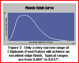
Chip Load
Once the correct tool geometry is chosen, the proper
 chip load is the next consideration. In mechanical-plastics
machining, the recommended chip load range is 0.004 to
0.012 ipt, which results in an excellent finish and acceptable
productivity rates (Figure 3). This narrow range
imparts the finest finish through the continuous generation
of properly sized or curled chips. Inadequate chip
load can lead to knife marks, which adversely affect the
finish. O-flute tools with a high rake and low clearance
help eliminate knife marks by slightly rubbing the part
during machining.
chip load is the next consideration. In mechanical-plastics
machining, the recommended chip load range is 0.004 to
0.012 ipt, which results in an excellent finish and acceptable
productivity rates (Figure 3). This narrow range
imparts the finest finish through the continuous generation
of properly sized or curled chips. Inadequate chip
load can lead to knife marks, which adversely affect the
finish. O-flute tools with a high rake and low clearance
help eliminate knife marks by slightly rubbing the part
during machining.
Machining Ways
Today’s CNC milling machines are
more than adequate to achieve the
proper feeds and speeds for router
tools. Spindle speeds of 10,000 rpm
and higher, with feed rates in excess
of 600 ipm, are not uncommon.
However, when these kinds of capabilities
are not available or feasible,
router tools toleranced for machining
mechanical plastics can perform at
spindle speeds of 6,000 rpm and proportionately
higher feed rates. The
key is maintaining proper chip load to
enhance productivity and part finish.
Drills for Mechanical
Plastics |
 Those machining mechanical
plastics have been at the
mercy of inappropriately designed
drills for years. Jobber
drills and similar tools are inadequate
in terms of producing
clear holes.
Those machining mechanical
plastics have been at the
mercy of inappropriately designed
drills for years. Jobber
drills and similar tools are inadequate
in terms of producing
clear holes.
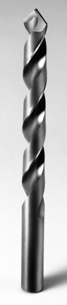
As with router tools
designed for machining
mechanical plastics,
drills are available
for soft plastics
that allow fast plunge
speeds and reduce
chip wrap. A 60°
point and flat-face
rake provide an ideal
plunging point. The
point reduces the
stresses introduced
into the hole walls and
imparts a fine finish
without clouding or
crazing (lines or tears
in the walls of the
hole) Drill with a
special
point for
mechanical
plastics. |
For more information, click on the author biography at the top of this page.
|