|
ROUTING: Preparing for Plastic Routing Part I
This article is the first of
a two-part series designed
to
help fabricators improve
their machining of plastics.
When companies make the
transition from the routing
of wood or aluminum
to the machining of plastics, there are
a number of preliminary procedures
and considerations that can help
ease the conversion and ensure a
smooth transition.
Periphery factors in the routing of
wood and aluminum can become some
of the most significant aspects of plastics
machining. Good planning and
preparation can help ease these factors
and the costs associated with the
startup of a new machining process.
This article is the first of a two-part
series that discusses the need to
have active preparation when making
the transition from wood routing to
plastic routing. Part 1 discusses the
CNC router and its associated hardware.
Part 2 will discuss tooling and
material selection.
Preparation of the
CNC Router
Routine maintenance of CNC
routers is a critical factor for ensuring
a high level of precision and repeatability
in finished parts. These maintenance
operations are defined by the
router manufacturers and are
absolutely essential when plastic
parts are to be machined. Minor
spindle vibration, gantry or bridge
shake and servo positioning errors
frequently have minor or unnoticeable
impacts in wood but can result
in scrap or expensive finishing operations
in plastic. The severity of these
problems is the direct result of
machine quality and adherence to
the manufacturer’s recommended
maintenance schedule.
Besides preventative maintenance,
there are additional steps that fabrication
companies can take to help
ensure a successful first run. Listed
below are some recommended actions
to consider before machining plastic.
Runout
The spindle, spindle mount and colleting
system should be checked for
the amount of TIR (Total Indicator
Runout). Tools required for verifying
TIR are: 0.001 inch or better dial
indicator,
 a magnetic indicator base,
a 6 inches or longer indicator stand
assembly and a long shank solid carbide
tool, a blank drill rod or blank
solid carbide round.
a magnetic indicator base,
a 6 inches or longer indicator stand
assembly and a long shank solid carbide
tool, a blank drill rod or blank
solid carbide round.
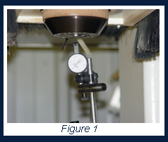
The first verification should be
made inside the spindle taper (see
Figure 1). The router or spindle manufacturer
should be able to provide
you with an acceptable upper limit for
TIR. An acceptable value is typically
0.001-inch TIR or better on older spindles and 0.0005-
inch TIR or better on newer spindles. There should be no
play in the radial direction of the spindle at any time.
The second verification
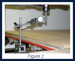 should be with a rod inserted
into the collet (see Figure 2). Measure the TIR at the furthest
point from the spindle. This measurement needs to
be taken multiple times with the rod being re-chucked and
rotated after each measurement. TIR is an additive property
and can vary depending on how the taper, collet,
chuck nut and rod align. The maximum reading is an indication
or true TIR. The colleting system should be better
than .002 inch total TIR for older machines and 0.001 inch total TIR for newer machines.
should be with a rod inserted
into the collet (see Figure 2). Measure the TIR at the furthest
point from the spindle. This measurement needs to
be taken multiple times with the rod being re-chucked and
rotated after each measurement. TIR is an additive property
and can vary depending on how the taper, collet,
chuck nut and rod align. The maximum reading is an indication
or true TIR. The colleting system should be better
than .002 inch total TIR for older machines and 0.001 inch total TIR for newer machines.
The third verification is dependent on whether the routing
involves any surface milling, pocketing or lettering. If
these operations are performed and require a high degree
of surface finish, the spindle should be verified perpendicular
to the work surface. This typically involves removing
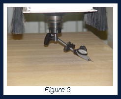 any spoilboards and setting the indicator as shown in
Figure 3. By finding the amount of tilt the spindle mount
has in both the X and the Y-axis, it is possible to determine
the degree of apparent machining marks that will be
seen on the bottom of a pocket cut.
Once the dial indicator is mounted in the spindle and
zeroed on the main table surface, rotate the spindle 180° by
hand and record the amount of TIV (Total Indicator Variance)
along both the X and Y-axis. The larger the TIV, the more
delineation will be seen during parallel pocketing cuts. This
effect is exaggerated by the use of larger diameter tools.
any spoilboards and setting the indicator as shown in
Figure 3. By finding the amount of tilt the spindle mount
has in both the X and the Y-axis, it is possible to determine
the degree of apparent machining marks that will be
seen on the bottom of a pocket cut.
Once the dial indicator is mounted in the spindle and
zeroed on the main table surface, rotate the spindle 180° by
hand and record the amount of TIV (Total Indicator Variance)
along both the X and Y-axis. The larger the TIV, the more
delineation will be seen during parallel pocketing cuts. This
effect is exaggerated by the use of larger diameter tools.
Collets
All collets and collet mating surfaces should be examined
and cleaned. Well-used collets should be considered
for replacement even if they are not showing obvious signs
of wear.
The following are collet replacement time recommendations:
- After 400-600 hours of runtime.
- A tool has broken in the shank.
- A tool has spun in the collet.
- A tool has been “short shanked” within the collet.
- The collet has been sprung.
Unlike the machining of wood where collet condition typically
has the greatest effect on tool life and breakage, collet
condition becomes apparent much sooner in plastics
machining where the product’s edge finish rapidly deteriorates.
There are specially designed felt and brass brushes
shaped for cleaning the insides of tapers and collets, and
these should be used during every shift change, every manual
tool change and every time a collet is changed.
There are various chemical cleaning products available for
routine collet maintenance, and they do a good job of removing
buildup that brushes cannot always eliminate. Petroleum
products should be avoided due to their ability to attract and
trap dust within the colleting system. Alcohol, citrus cleaners
and other formulations are good alternatives.
Vacuum
Vacuum systems should be evaluated for their ability to
hold small or thin parts. Many plastic sheet parts and/or
thermoformed parts are much more difficult to hold due to
their size, shape and comparably light weight. By taking
steps to increase the amount of usable vacuum, fabricators
can reduce the amount of time spent on custom fixtures and
typically achieve higher feed rates with better cycle times.
Flow through systems should be evaluated for: -
Pump Size - 800 cfm or greater for a 4-foot by 8-foot
table.
-
Spoilboard - lightweight, porous MDF with a reasonable
thickness and the edges sealed to reduce air leakage.
- Supply Lines - evaluate for diameter and quantity. Flow
through systems benefit greatly from multiple large
diameter supplies. Consider using two or more 4-inch or
larger supply lines for each table.
Discreet (or dedicated) systems should be evaluated for:-
Pump Size - 25 in Hg or better vacuum at full sealed
vacuum conditions.
-
Spoilboard - should be channeled to provide best vacuum
dispersion and sealed all around to prevent leaks.
- Supply Lines - multiple 1/2” diameter or larger lines are
recommended.
Dust Collection
It is possible to have both too much and not enough
dust collection at the same time. Dust collection systems
serve two purposes: to remove the chips from the work
area and to keep the spindle and tool cool. Dust collectors
that are under-powered can reduce spindle life and produce
poor quality finishes by not extracting chips from the
cut path. These chips and their associated heat can ruin
otherwise acceptable finishes. Over-powered dust collection
with rigid dust brushes can overwhelm vacuum hold
down fixtures for small parts and cause part movement or
part ejection. Care should be given to the evaluation of
the role of the dust collector for each job.
Coolant
While mist or liquid coolants typically are an
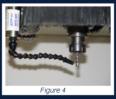 unacceptable addition for most CNC plastic routing
applications, air coolant systems should be seriously
considered. A simple air nozzle (see Figure 4)
directed at the cutting bit can dramatically improve
cut quality and tool life. The air serves to cool the
tool and cut path, remove warm chips, and reduce
the instances of chip wrap around the cutter.
unacceptable addition for most CNC plastic routing
applications, air coolant systems should be seriously
considered. A simple air nozzle (see Figure 4)
directed at the cutting bit can dramatically improve
cut quality and tool life. The air serves to cool the
tool and cut path, remove warm chips, and reduce
the instances of chip wrap around the cutter.
Another option is to use a cooling nozzle. These
devices go by various names (cool gun, cold gun,
Venturi gun) and use a Venturi orifice to significantly
reduce the temperature of the air flowing
from the nozzle. By using chilled air, cutter life and
cut quality can be considerably extended. A drawback
is that the velocity of the air is significantly
reduced. This reduces the ability of the nozzle to
remove chip wraps and requires that it be placed
closer to the router bit to overcome the air dispersal
associated with the dust collector.
By evaluating the above machine factors before
beginning a plastic routing operation, the chances
of success and profitability can be significantly
improved.
The next article will cover the topics of tool selection
and material selection before actual machining
takes place.
For more information, click on the author biography at the top of this page.
|