|
ROUTING: Routing Acrylic
Routing Acrylic Plastic can be classified as soft or hard for routing purposes. The characteristics of each classification necessitates the use of different router tooling with varying geometry. Acrylic has the attribute of being either soft or hard depending on the manufacturing process. Extruded acrylic tends to fall on the soft side of the equation, while cast acrylic is hard. Manufacturers have designations for each type of acrylic and the user should be aware of the differences because it makes a huge impact on the type of router tooling utilized.
Tool Selection
Once the condition of the acrylic is established, tool selection becomes a matter of choosing a router tool that satisfies the needs of the user
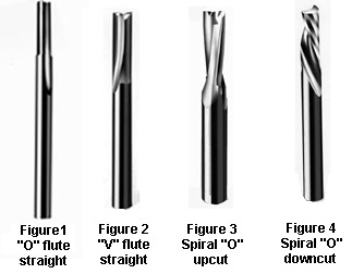
Generally speaking, "O" flute tools (Figure 1) are used for soft acrylic, while "V" flute tools (Figure 2) are appropriate for hard acrylic.
These tools are offered in straight and spiral upcut and downcut configurations, (Figure 3 and Figure 4) and may be manufactured from high-speed steel, carbide tipped or solid carbide. High-speed steel and carbide tipped tooling with steel bodies are more
appropriate for hand fed routing, while solid carbide is best utilized in the more rigid and accurate environment of the CNC router. The choice of straight flute tooling versus spiral flute depends on the application and the way the user wants to influence the chip. Straight flute tools have no influence, while the spiral flute tooling can move a chip upward or downward.
Thermoformers tend to use straight or downcut spirals because of the neutral or downward effect on the part being routed, while sheet fabricators prefer the upcut spiral, which enhances chip removal.
Besides chip influence, the diameter and number of cutting edges of the router tool have an important bearing on the productivity and the ultimate finish of acrylic parts. Larger diameter tools with more gullet area inside the flute of the router tools provide for faster feedrates and accentuate stability, which has a positive effect on the finish. Increasing the number of cutting edges also influences finish. There can be a significant difference in edge finish from a single edge tool to a multi-edge tool.
However, there are points of diminishing return, and the user should weigh all factors when choosing diameter and number of cutting edges. The diameter should be large enough to accommodate finish requirements, dissipate chip and maximize yield.
 A case in point is the three edge finisher (Figure 5), which does an excellent job in cast acrylic, but must be utilized in 3/8" diameter or above to provide enough gullet space in the flute for adequate chip removal. At the same time, single edge tools should not be applied in diameters larger than 3/8" because of balance concerns. These general guidelines for tool selection in acrylic can be further quantified by visiting www.plasticrouting.com. This website provides specific tool recommendations based on a variety of sheet manufacturers offering acrylic material.
Feeds, Speeds And Chipload
After tool selection, the question of proper feed and speed to best utilize the tool becomes essential. In CNC routing, the user manipulates the feed and speed of the router to arrive at an acceptable chipload. The chipload (or thickness of the chip) influences the finish of the part, the life of the tool and ultimately the productivity of the routing operation. A thicker chip removes heat, the natural enemy of a cutting edge, but too much chipload can adversely affect edge finish. The ideal chipload for acrylic seems to be somewhere between 0.004-0.012 to accommodate the issues of tool life and acceptable finish requirements. To get an acceptable chipload for a specific application, the user should determine the feedrate to achieve a 0.006 chipload (Chipload = feedrate/(rpm x # cutting edges) and examine the routed edge. If the edge shows a white or chalky appearance or chips are rewelding, the feedrate should be increased. If the edge finish of the part has a rough, crater-like appearance, the feedrate should be reduced. Since chipload is determined by feedrate and spindle speed, the spindle speed can be reduced to achieve appropriate chipload. Regardless, the ultimate goal is to find the proper chipload to achieve the best tool life at a profitable cycle time with excellent finished parts.
Rigidity And Concentricity
Tool selection and proper chipload are all for naught if the operation is not conducted in an environment which insures rigidity and concentricity. In terms of rigidity, this applies equally to the machine itself and to the fixturing of the components to be routed. The machine, whether it be hand fed or CNC, must be maintained to manufacturer specifications. Collets, collet nuts and tool holders must be cleaned after each tool change. For proper collet maintenance, collets should be replaced every 400-600 hours of run time, and collet nuts should be replaced as they show wear. Proper machine maintenance allows acrylic parts to be routed with a tool that follows the correct tool path in a concentric fashion.
While machine rigidity and concentricity are vital to consistent performance, fixturing is equally important to surface finish on each routed part. Fixtures should be rigidly built and mounted to the work surface. Vacuum supply should be oversized whenever possible and hard fixturing should be securely mounted without opportunity for movement. Also, friction enhancements such as rubberized coatings and gasketing sheet foam may be utilized. All these elements will keep vibration to a minimum. Rigidity and concentricity are the key factors to improve productivity and edge finish through the stability of the machine and the parts. Specific recom-mendations in these two areas can be found by visiting www.allstaradhesives.com or by ordering the soon-to-be-released CNC Production Routing Guide by Onsrud Cutter LP, (Figure 6).
Specialty Tools For Acyrlic
Refinements continue to be made in the area of edge finishing, shaping and drilling acrylic. In the past, these operations were mostly accomplished with tools designed for the wood- or metal-working industry and did not have the proper geometry to accommodate plastic. Today, tools are readily available with plastic geometry to provide specialty cuts with outstanding results. Edge rounding router bits are available in "O" flute, "V" flute (Figure 7), or spiral "O" flute configurations with single or double edges. The general guidelines mentioned in the first part of this article would dictate the choice of flute configuration. The tools provide a full radius on the edge of the part for an excellent finish.
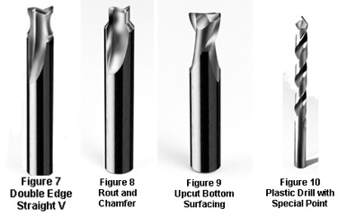
The solid carbide rout and chamfer bit (Figure 8) was designed to provide up to 1/16" top face chamfer and a finished side edge on acrylic parts.
This multi-faceted design allows the CNC user to perform what was ordinarily a two step process and complete the task in one pass without a tool change.
The bottom surfacing router bit in solid carbide upcut geometry (Figure 9) provides a swirl-free bottom in pocketing or lettering applications. The tool utilizes a near flat point with radiused corners to create a smooth bottom with aesthetically pleasing results.
In the area of drilling, a drill with a 60-degree point and flat rake face (Figure 10) provides fast plunging with reduction of chip wrap, tearout and minimized lifting of parts. The point reduces the stresses introduced into the hole walls and will provide a clean hole surface without the clouding typical in standard jobber drills.
Acrylic is a widely utilized material that machines effectively in hand fed as well as CNC routing applications. The key is choosing the right-tool-for-the-job, which is based on knowing the condition of the material and operating in a rigid environment with proper chipload. When these parameters are met, the two important factors of edge finish and productivity are achieved with excellent results.
For more information, click on the Author Biography link at the top of this page.
|