|
ROUTING: Real World Routing Solutions
This article is the third in a four
part series designed to bring to light
some common routing problems and
the tooling and/or process changes that
became the solutions to the problems.
CNC routers continue to
improve and enable users to
do more in less time. As the
rigidity, fixturing, feed rates, spindle
capabilities and ease of programming
for CNC routers increase every
year, tooling must keep pace. Cutting
tools must not only be geometrically competent to meet
the technology challenge, they must be application-specific.
The days of generic “one tool does it all” router bits
are over. The tool must be optimized for the job as a part
of the setup.
Scenario 7
 Material Cut: 1/8-inch acrylic
Product: Plaque faces
Router Type: 3-axis CNC
Feeds & Speeds: 18,000 rpm at
100 ipm
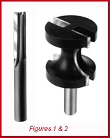
Initial Tooling: 1 pass with CT
straight, 1 pass CT radius (Figures 1 & 2)
Problem: Long cycle time
required to complete
product, resulting in
unacceptable cost.
In this application, the
fabricator wanted to
accomplish a two-step
process in one pass; two
passes were too time
consuming and expensive.
In addition, when
the radius tool made a
final pass on the part,
either the paper-masking
or the polymasking
would
be torn in such a way that it was unacceptable
to ship the part without re-masking. The
goal was
 to be able to cut the part cleanly
with one pass and be able to ship the parts
right off of the router.
to be able to cut the part cleanly
with one pass and be able to ship the parts
right off of the router.
By choosing a solid carbide bit with a radius
ground into the cutting edge, the customer
had excellent results and was able to cut the
parts and radius at the same time at a much
higher feed rate (Figure 3). No re-masking was
necessary either, and the fabricator accomplished
his goal in a timely manner.
Scenario 8
 Material Cut:
 Acrylic with laminated aluminum face
Product: Back light lettering for signs
Router type: 3-axis CNC
Feeds & Speeds: 18,000 rpm at 40 ipm
Initial Tooling: Solid carbide metalworking
end mills
Problem: The plastic and aluminum were
welding together after being cut.
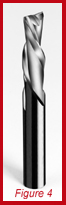
The sign manufacturer was trying to
machine dissimilar materials at the same
time. The tools that cut
 the aluminum well
performed poorly when cutting the acrylic
(Figure 4). The tool that cut the acrylic well
performed poorly and left a burr on the aluminum.
The problem was that cutting the
acrylic required a very sharp edge, as did the
aluminum, but the edge geometry of the two
materials differed.
the aluminum well
performed poorly when cutting the acrylic
(Figure 4). The tool that cut the acrylic well
performed poorly and left a burr on the aluminum.
The problem was that cutting the
acrylic required a very sharp edge, as did the
aluminum, but the edge geometry of the two
materials differed.
Metalworking tools normally have a large
cross-section that limits the size of the chip formed.
Unless a large enough chip is formed, it cannot be
thrown clear. Thus it is re-cut, usually resulting in rewelding
of the chip back to the base material. Selecting
the right geometry was critical in this case with the aluminum
laminate on the top of the material.
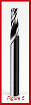
It took a specialized tool design of a solid
carbide O flute spiral upcut router bit. It was
 critical to use an upcut tool due to the chip
extraction. A small (3/16-
inch) bit was required due
to the inside radius in the
corners of the letters
(Figure 5). To overcome the
upcut tool’s tendency to lift
the part, the manufacturer
was required to cut all the
way through the aluminum
laminate and acrylic, but
not the paper masking on
the bottom side of the
acrylic.
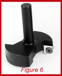
The company was able to accomplish
this by first planing the table
true with a spoilboard-
surfacing
tool,
allowing a
consistent
plane to be
maintained
(Figure 6). Then,
by not cutting
through the paper
masking,
they were
able to hold parts in place.
critical to use an upcut tool due to the chip
extraction. A small (3/16-
inch) bit was required due
to the inside radius in the
corners of the letters
(Figure 5). To overcome the
upcut tool’s tendency to lift
the part, the manufacturer
was required to cut all the
way through the aluminum
laminate and acrylic, but
not the paper masking on
the bottom side of the
acrylic.
The company was able to accomplish
this by first planing the table
true with a spoilboard-
surfacing
tool,
allowing a
consistent
plane to be
maintained
(Figure 6). Then,
by not cutting
through the paper
masking,
they were
able to hold parts in place.
Scenario 9
Material: 1/4-inch polyethylene
Product Fabricated: Office machine housing
Router type: 5-axis CNC
Feeds & Speeds: 18,000 rpm at 50 ipm
Initial Tooling: Carbide tipped straight
Problems: Poor and inconsistent edge quality, bird
nesting when making holes
The fabricator was utilizing a 1/2-inch
diameter carbide-tipped tool designed for
 cutting wood and getting mixed results in
the finished quality of the edge (Figure 7).
The part was a large one, with many planes
to be cut, and required both a long extension
from the spindle, as well as a long cutting
edge length. The tool performed a
number of operations, including interpolating
holes and perimeter trimming.
cutting wood and getting mixed results in
the finished quality of the edge (Figure 7).
The part was a large one, with many planes
to be cut, and required both a long extension
from the spindle, as well as a long cutting
edge length. The tool performed a
number of operations, including interpolating
holes and perimeter trimming.
While the perimeter trimming was a relatively
easy operation, it resulted in an
inconsistent finish and could not be run as
fast because the machine would cut without
chattering. The holes to be interpolated
were also a problem due to “bird nesting” of the
chips when the tool plunged into the workpiece.
This is a common problem in 5-axis CNC routing. It
is a result of tool selection and programming technique.
The tool rotating at 18,000 rpm comes into contact
with the part 300 times a second if it is a single
edge design. While plunging at a feed speed of 40 to
50 ipm, the tool is not allowed to cut a large enough
chip to adequately expel the chip from the cut. This
inability to expel the chip causes a string or thread to
form and wrap itself around the tool. While initially not
causing much of a problem, the “bird nesting” continues
to grow and as the “nest” gets larger, scratching
begins to occur.
This requires the operator to stand there with an air
 tool and continuously remove the chip build-up. This not
only wastes time, it can be dangerous and usually results
in inconsistent quality of parts requiring some secondary
processing.
tool and continuously remove the chip build-up. This not
only wastes time, it can be dangerous and usually results
in inconsistent quality of parts requiring some secondary
processing.
The best way to eliminate this type of problem is to
reduce the rpm and increase the feed rate. RPM’s for
hole making should be reduced to 8,000-9,000, allowing
the tool to cut a large chip, throwing it free from the
cut and eliminating build-up on the tool. Feed rate
should be increased to approximately 150 ipm.
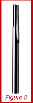
This, combined with the selection of proper geometry
plastic tools, allows for excellent hole making
and, with a change in rpm and feed rate,
excellent perimeter routing. In this case, a
1/4-inch diameter tool was able to not only
eliminate the “bird nesting” problem, but
also to run much faster on the perimeter
due to the reduced resistance offered by the
1/4-inch tool in a single edge O flute design
(Figure 8).
The bit design selected was a straight tool.
Even though a spiral might help chip ejection,
it would cause other hold-down issue problems
while cutting the perimeter of the part.
Each of these examples illustrates the fact
that tools designed specifically to cut plastic
provide a better solution when plastic materials
are machined. Plastic tools have sharper
edges because they have a higher angle of
cut. This enables the chip to be quickly removed and
the piece part to have a better finish.
For more information, click on the author biography at the top of this page.
|