|
Bearing Design
Bearing Design
Nylon materials intended for bearing applications with or without lubrication must be designed with consideration of the individual physical characteristics and operating conditions of each actual requirement. The design data below is provided as an introduction to nylon bearing design for materials manufactured by Cast Nylons Limited, others may vary. Where operating conditions are unknown or questionable, it is suggested that field testing be conducted.
Guidelines For Bearing Design
PV value The frictional build-up of heat is a major consideration in the design of nylon bearings. The two significant factors that affect heat generation are unit pressure (P) and surface velocity (V). Pressure Velocity (PV), therefore, is the product of unit pressure and surface velocity.
Surface velocity for sleeve-type bearings can computed using the following:
V = .262 x rpm x D
Rpm represents shaft revolutions per minute, and D is the shaft diameter in inches.
Pressure can be computed for flat bearing units by dividing the total load in pounds by the contact area expressed in square inches:
P = Total Load / Contact Area
For sleeve bearings, the total load is divided by the projected area of the bearing surface (bearing I.D. in inches x bearing length in inches). Once pressure and surface velocity are known, PV can be determined by using the following:
PV = P x V
Now that PV has been determined for the application, it must be checked against the PV limits for NYCAST materials as listed below.
|
Limiting PV Values |
| |
Unlubricated |
Continuously Lubricated |
|
NYCAST 6 PA
6 PA-Blue, 6PA-MoS2 |
3,600 |
14,000 |
|
NYCAST CP |
3,600 |
14,000 |
|
NYCAST NYLOIL |
16,000 |
16,000 |
Note: Max. P for dynamic bearings is 2,000 psi. Max. V for dynamic bearings is 400 fpm.
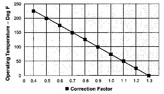
Ambient Temperature Correction
When the ambient temperature is higher or lower than 75 F, the PV capabilities change. The following graph indicates the relationship between ambient temperatures and the necessary PV modifications. From the graph below, establish the Ambient Temperature Correction Factor for the bearing operating environment temperature and multiply this value by the limiting PV for the material being used. The value obtained is the actual limiting PV value for the application in question. For a Nycast Nyoil bearing operating in a 150°F environment, the temperature correction factor would be 0.7, multiplying 16,000 x 0.7 produces a new limiting PV value of 11,200.
Ambient Temperature Correction Factors
Basic Nylon Bearing Design
Nominal Wall Thickness In the design of new equipment, the engineer has some latitude in establishing nominal wall thickness. For bearings that will be subjected to severe impact, maximum walls are suggested, while minimum walls can be used for bearings that operate near the material's maximum recommended PV. Nominal Wall thickness is the difference between shaft diameter and the housing LD. divided by 2.
Bearing Shape The ratio of bearing length to shaft diameter has an important effect on the coefficient of friction. For a bearing with a ratio of one (bearing length equal to shaft diameter), the coefficient is generally lowest. As the bearing length increases to two or three times the diameter of the shaft, the probability of localized heating increases due to slight shaft vibration and out-of-roundness.
Clearance Because the clearances required for nylon bearings are larger than those normally required for metal bearings, attention to proper clearance is one of the most important factors in bearing design. Most premature nylon bearing failures occur because of insufficient initial clearance that results in seizure on the shaft and even melting of the bearing. Because of the self-dampening nature of nylon materials, the increased clearances required do not result in shaft vibration or scoring of the bearing.
Total running clearance can be calculated by adding the basic shaft allowance (C1), the wall thickness allowance (C2), the press fit allowance (C3), and, if applicable the moisture expansion allowance (C4). This running clearance is then added to the shaft diameter to obtain an actual I.D. for the bearing. For press fit bearings, the O.D. should be machined to the nominal I.D. of the housing plus the press fit allowance C3.
Machining Tolerance Machining surface finish of the bearing and mating shaft are important for satisfactory operation, testing has shown that finishes of 32 RMS produce the lowest heat generation and bearing wear. Proper running clearances for bearing I.D. and O.D. can be assured by holding tight machining tolerances. It is recommended that I.D.s be machined to plus best commercial tolerance, minus 0.00 inches. O.D.s should be machined to plus or minus best commercial tolerance.
Lubrication Except where dry applications are required (as in some food and textile machinery), lubrication should always be used. The lubrication of the nylon bearing results in a higher PV limit on sliding parts when compared to dry operation. Any general-purpose grease or oil can be used, providing that they do not contain acids. Acid containing lubricants cause a swelling of the nylon material, which decreases the clearance and can cause seizure on the shaft. An initial start-up application of grease or oil will facilitate bedding-in and increase both bearing performance and life, even if no further lubricant is provided during operation.
|
C1 Shaft Allowance |
|
Shaft Diameter (inches) |
1 |
2 |
3 |
4 |
5 |
6 |
7 |
8 |
9 |
10 |
11 |
12 |
|
C1 |
.005 |
.009 |
.012 |
.014 |
.017 |
.019 |
.021 |
.024 |
.026 |
.028 |
.030 |
.032 |
Shaft allowance, C1 is the normal running clearance required on the bearing I.D.
|
C2 Wall Thickness Allowance |
|
Material |
Average
Bearing Temp. |
1/8" |
1/4" |
3/8" |
1/2" |
5/8" |
3/4" |
1" |
1 Ľ" |
1 ˝" |
|
All NYCAST
Materials
(Operation
in normal
surroundings
at 50% RH |
75°F |
.002 |
.004 |
.006 |
.007 |
.009 |
.011 |
.015 |
.019 |
.022 |
|
100°F |
.002 |
.004 |
.006 |
.008 |
.010 |
.012 |
.016 |
.020 |
.024 |
|
125°F |
.002 |
.004 |
.007 |
.009 |
.011 |
.013 |
.018 |
.022 |
.027 |
|
150°F |
.002 |
.005 |
.007 |
.009 |
.012 |
.014 |
.019 |
.024 |
.028 |
|
175°F |
.002 |
.005 |
.007 |
.010 |
.013 |
.016 |
.021 |
.026 |
.031 |
|
200°F |
.003 |
.006 |
.008 |
.011 |
.014 |
.017 |
.023 |
.028 |
.034 |
|
225°F |
.003 |
.006 |
.009 |
.012 |
.015 |
.018 |
.024 |
.030 |
.036 |
|
250°F |
.003 |
.006 |
.009 |
.013 |
.016 |
.019 |
.026 |
.032 |
.039 |
(Data given is for bearings with ends free to expand. When ends retained, increase values by 50%)
C2 is the clearance required in the bearing I.D. to allow for expansion of the bearing wall during operation.
|
C3 Press Fit Allowance |
|
Housing I.D. (inches) |
0 |
1 |
2 |
3 |
4 |
5 |
6 |
7 |
8 |
9 |
10 |
11 |
12 |
|
C3 |
.002 |
.004 |
.006 |
.009 |
.010 |
.012 |
.013 |
.014 |
.015 |
.016 |
.017 |
.018 |
.019 |
Press fit allowance, C3 is added to bearing I.D. when bearing is pressed into a housing. When NYCAST materials are pressed into a housing the bearing experiences close-in. C3 added to the bearing I.D. allows for this close- in.
|
C4 Moisture Expansion Allowance (Submerged/water lubricated applications only) |
|
Bearing Wall Thickness (inches) |
1/8" |
3/16" |
1/4" |
3/8" |
1/2" |
3/4" |
1" & over |
|
C4 |
.012 |
.017 |
.021 |
.026 |
.030 |
.032 |
.033 |
Figures shown represent maximum bearing I.D. closure as a result of bearing wall expansion at full moisture saturation and must be added to the bearing I.D. for correct clearance.
Written by Michael Worthington, Chief Engineer for Cast Nylons, Limited, manufacturers of NycastŇ
rod, sheet, tubular bars, discs rings, custom castings and NymetalŇ
, NyloilŇ
, NycastŇ
12 and NycastŇ
RX and GX solid lube-filled materials.
For more information, contact Cast Nylons Limited, 4300 Hamann Parkway, Willoughby, OH 44094, 800-543-3619, Fax: 440-269-2323, E-mail: sales@castnylon.com, Web: www.castnylon.com.
|